Matchless Info About How To Control Igbt
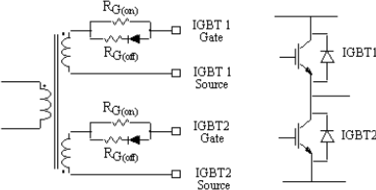
When a positive voltage (typically +15 vdc) is applied to the gate the igbt will turn on.
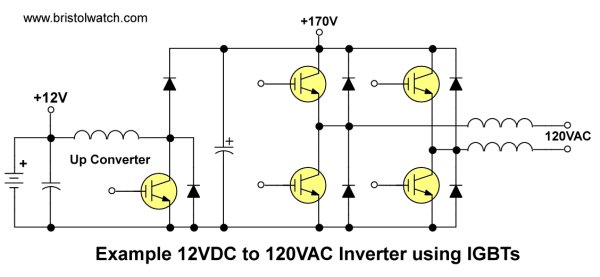
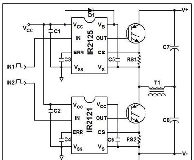
How to control igbt. Incorporation of dead band in the complementary igbt drive waveforms. A typical switching circuit of igbt is shown below, the gate volt v g is applied to the gate pin to switch a motor (m) from a supply voltage v+. Drive because their control electrode is isolated from the current conducting silicon, therefore a continuous on current is not required.
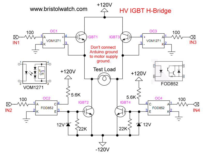
An igbt is simply switched “on” and “off” by triggering and disabling its gate terminal. In a classic inverter, a forward conducting igbt is turned off at the start of the interlock time period. Support me for more videos:
This pwm wave is key to a vfds operation because it is the variable voltage and frequency created by the pwm wave that will allow a vfd to control the speed of the motor. How do i trigger igbt? For the opposite diode, this means that first, the blocking voltage.
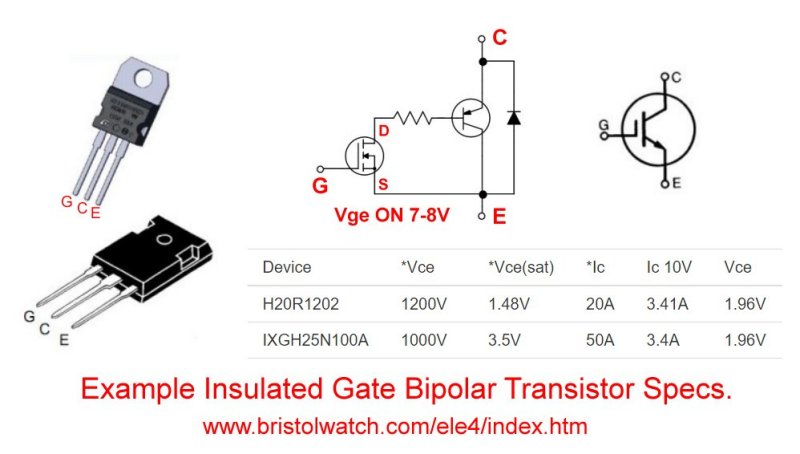
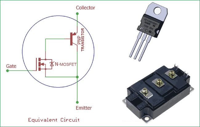
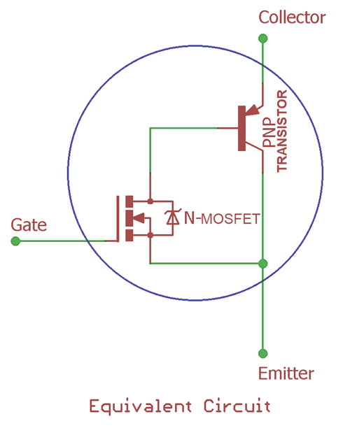
A vfd igbt consists of a gate, collector and an emitter. The igbt is simulated as a series combination of a resistor ron, inductor lon, and a dc voltage source vf in series with a switch controlled by a logical signal (g > 0 or g = 0). A constant +ve voltage i/p signal across the 'g' and the 'e' will retain the device.
About press copyright contact us creators advertise developers terms privacy policy & safety how youtube works test new features press copyright contact us creators. For conditions where the ambient temperature tc is = 25℃ or lower, the igbt collector dissipation is applied in accordance with their absolute maximum rating. The resistor rs is roughly used to.
Incorporation of a soft start algorithm in the mcu firmware to limit inrush currents. On/off control, pwm control, or what?


